-
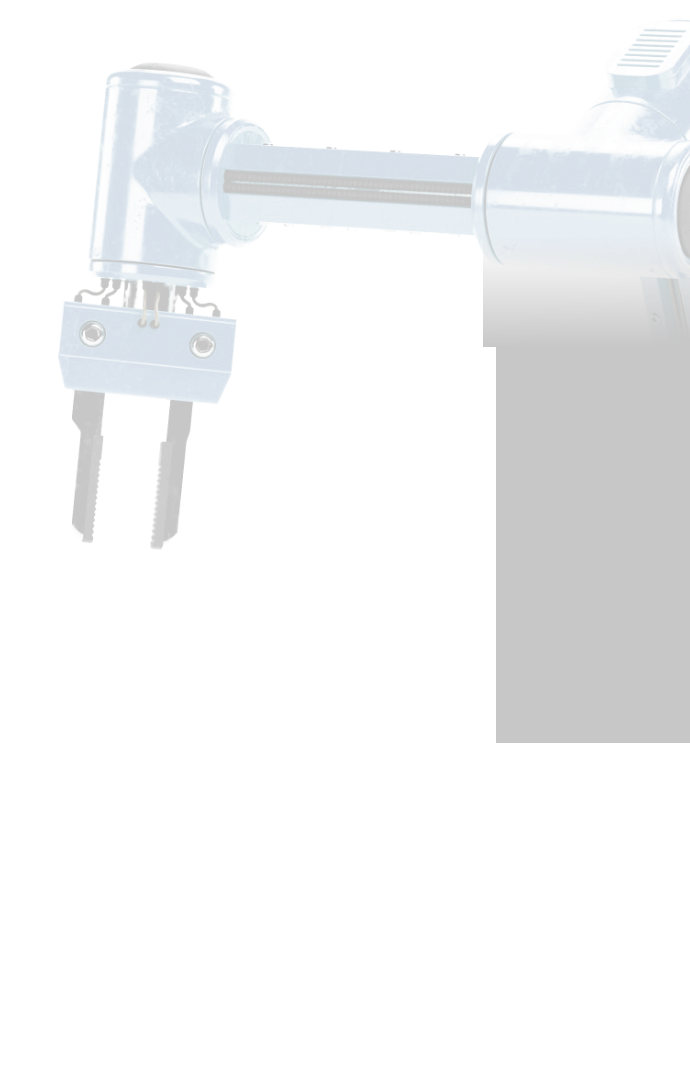
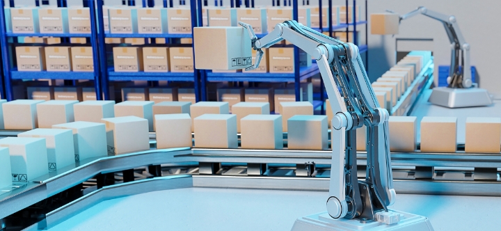
3D Data Acquisition
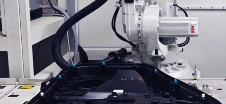
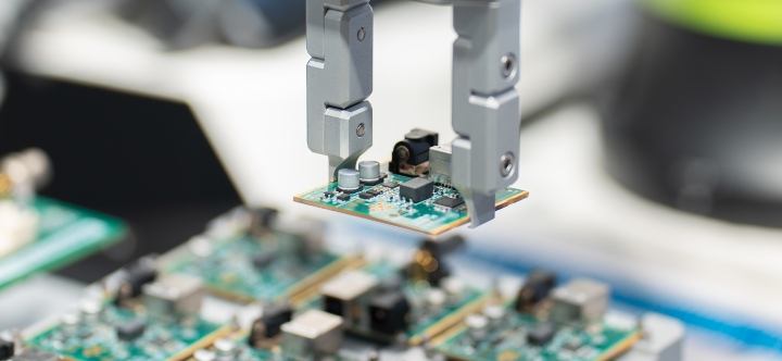
A 3D sensor (Eye-in-Hand) mounted on the robot gripper acquires 3D shape data (Point Cloud) of the work target. -
Automatic Calibration
Performs hand-eye calibration that automatically calculates the transformation matrix between sensor and robot with high precision in a short time. -
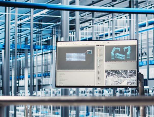
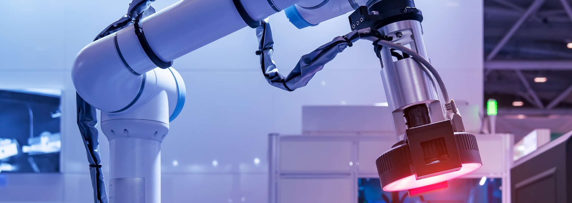
VRC (Vision-Guided Robot Control)
Transmits 6DoF (6 Degrees of Freedom: 3 position axes, 3 orientation axes) errors of work targets measured by the vision system to the robot controller in real-time, immediately modifying and correcting robot paths. This real-time feedback loop dramatically improves work success rates for irregular objects.
PRINCIPLES
Hand-Eye Calibration & Real-Time Correction
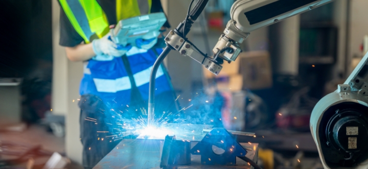
Traditional manual robot programming methods cause serious problems and potential losses in manufacturing environments.
This problem is maximized especially in collaborative robot operating environments where flexibility and ease of use are key.
This problem is maximized especially in collaborative robot operating environments where flexibility and ease of use are key.